UCVM 13.9.0
Contents
Introduction
Unified Community Velocity Model (UCVM) software framework is a collection of software tools designed to provide standard interface to multiple, alternative, California 3D velocity models. One important use of UCVM is in high resolution 3D wave propagation simulations for California. UCVM development is an interdisciplinary research collaboration involving geoscientists and computer scientists. UCVM geoscience research includes identification and assembly of existing California velocity models into a state-wide model and improvements to existing velocity models. UCVM computer science research includes definition of a easy-to-use CVM query interface, integration of regional 3D and geotechnical models, and automated CVM evaluation processing capabilities.
Download
| Platform | File | Download | Mirror |
|---|---|---|---|
| Linux | SCEC UCVM 13.9.0 Official Release (391 Mb) | ucvm-13.9.0.tar.gz | N/A |
| Linux | SCEC UCVM 13.9.0 md5 checksum (< 1Kb) | ucvm-13.9.0.tar.gz.md5 | N/A |
User Guide
We strongly recommend that you read through the UCVM user guide for more information on how to install and use UCVM.
Developer's Guide
Learn how to integrate your own velocity models and add other functionality to UCVM by visiting the UCVM developer guide.
Issue Tracking System
Users can report issues, bugs, and request features using the UCVM Trac system. Requires a SCEC login.
Supported Model List
UCVM supports the following 3D velocity models:
- CVM-S4
- CVM-H 11.9.1
- CVM-S4.23
- CenCal 0.8.0
- SCEC CVM-NCI
- Magistrale Wasatch Front CVM
- Graves Cape Mendocino
- Lin-Thurber Statewide
- Tape SoCal
Additional Functionality
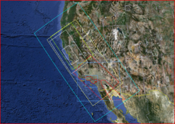
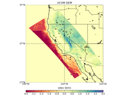
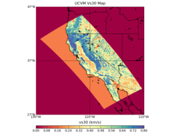
The following is the coverage region and projection for the included 2D elevation and Vs30 maps. The entire state of California is included, along with portions of Oregon, Nevada, Arizona, and northern Mexico.
DEM
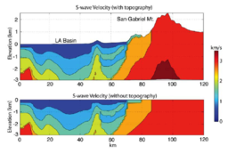
A statewide DEM for the proposed coverage region is included within UCVM. Elevation data has been sampled from USGS NED 1 arcsec dataset (~30 m), and bathymetric data from the NOAA ETOPO1 1' dataset (~1.5 km). This DEM is currently sampled at a resolution of approximately 220m but this may be increased. The elevation data is stored as a fixed resolution Etree for the entire 1800 x 900 km region. The elevation at a particular point is smoothed using bilinear interpolation of the surrounding four elevation octants.
Vs30 Maps
Two statewide Vs30 maps for the proposed coverage region are included within UCVM:
- Wills-Wald Vs30 map (default): Vs30 data for the California landmass has been sampled from the Wills (2006) dataset at approx 0.0002197 D resolution, and out-of-state/ocean areas have been sampled from the Wald (2007) dataset at 0.0083333 D resolution.
- Yong-Wald Vs30 map (optional): Vs30 data for the California landmass has been sampled from the Yong (2011) dataset at approx 0.013 D resolution, and out-of-state/ocean areas have been sampled from the Wald (2007) dataset at 0.0083333 D resolution.
These maps are currently sampled at a resolution of approximately 220m but this may be increased. The Vs30 data is stored as a fixed resolution Etree for the entire 1800 x 900 km region. The Vs30 value at a particular point is smoothed using bilinear interpolation of the surrounding four map octants.
Geotechnical Layer
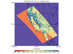
A statewide GTL for the proposed coverage region is included within UCVM. This is based on the Vs30-derived GTL method developed by Ely (2010). Interpolation between this GTL and the underlying crustal models is accomplished with the interpolation method described in that same publication. The z range over which interpolation is performed is configurable, as is the interpolation method used. The Ely method takes its input Vs30 value from the Vs30 map included within UCVM (described in the previous section).
Additionally, UCVM is able to support any number of other user-defined GTLs. It will combine them in a manner analogous to how the crustal models are combined. Each GTL may also have its own user-defined interpolation function that is used to blend it with the underlying crustal models. If no interpolation method is specified, linear interpolation is assumed.
Ability to Combine Regional Models
The UCVM API currently combines models by simply tiling them in a user-specified order. The software also provides a post-processing "patching" mechanism to smooth out discontinuities at the interfaces between different regional models. The user identifies a 3D geographic region in the form of an open box where smoothing is to be performed. A patcher is run to extract the material properties along the surfaces of this box at a fixed resolution (eg: 250 m) and it saves them into a new model which may then be imported into and queried by UCVM. Points that fall within the smoothing region are interpolated using an inverse distance weighting function with the 10% closest surface points on the same z-plane. A power factor of 2.0 is used for weighting. Linear interpolation is used along the z-axis to smooth out the edge values.
The following series of images show how this process works:
Exporting to Etree
Any number of regional models and GTLs may be combined into a single meta-model and then exported to an Etree with variable resolution. The local resolution at a particular point is determined with the following relation:
local rez <= local Vs / (fmax * ppw)

where:
local rez : the local resolution in meters
local Vs  : the local minimum Vs in meters/sec
fmax      : desired max frequency to support in Hz
ppw       : points per wavelength
UCVM Background Material
Numerous resources are available which help explain more about UCVM and the history of its development.
- UCVM Poster From SCEC Annual Meeting 2013
- UCVM Poster From CIG-QUEST Workshop 2013
- UCVM Talk From CIG-QUEST Workshop 2013
Learn more about each CVM as well:
CVM-S
CVM-H
- CVM-H Wiki Page
- Harvard Structural Geology & Earth Resources Group
- Collection of Presentations about CVM-S and CVM-H (56Mb ppt file)
Lin-Thurber CVM
Wasatch Front CVM
Other
Source Code & Issue Reporting
Report issues and feature requests on our Trac site.
References
- Ely, G., T. H. Jordan, P. Small, P. J. Maechling (2010), A Vs30-derived Near-surface Seismic Velocity Model Abstract S51A-1907, presented at 2010 Fall Meeting, AGU, San Francisco, Calif., 13-17 Dec. [Ely2010-AGU.pdf]
- Graves, R. (1994), Rupture History and Strong Motion Modeling of the 1992 Cape Mendocino Earthquake, USGS External Grant Report
- Lin, G., C. H. Thurber, H. Zhang, E. Hauksson, P. Shearer, F. Waldhauser, T. M. Brocher, and J. Hardebeck (2010), A California statewide three-dimensional seismic velocity model from both absolute and differential Times, Bull. Seism. Soc. Am., 100, in press. supplemental
- Taborda R., López J., O'Hallaron D., Tu T. and Bielak J. (2007), A review of the current approach to CVM-Etrees, SCEC Annual Meeting, Palm Springs, CA, USA, September 8–12. [1]
- Thurber, C., H. Zhang, F. Waldhauser, J. Hardebeck, A. Michael, and D. Eberhart-Phillips (2006), Three-dimensional compressional wavespeed model, earthquake relocations, and focal mechanisms for the Parkfield, California, region, Bull. Seism. Soc. Am., 96, S38-S49, 2006. supplemental
- Thurber, C., T. Brocher, H. Zhang, and V. Langenheim (2007), Three-dimensional P-wave velocity model for the San Francisco Bay region, California, J. Geophys. Res., 112, B07313, doi:10.1029/ 2006JB004682, 2007.
- Thurber, C., H. Zhang, T. Brocher, and V. Langenheim (2009), Regional three-dimensional seismic velocity model of the crust and uppermost mantle of northern California, J.Geophys. Res., 114, B01304, doi:10.1029/2008JB005766, 2009.
- Wald, D. J., and T. I. Allen (2007), Topographic slope as a proxy for seismic site conditions and amplification, Bull. Seism. Soc. Am., 97 (5), 1379-1395, doi:10.1785/0120060267.
- Wills, C. J., and K. B. Clahan (2006), Developing a map of geologically defined site-condition categories for California, Bull. Seism. Soc. Am., 96 (4A), 1483-1501, doi:10.1785/0120050179.
- Yong, A., Hough, S.E., Iwahashi, J., and A. Braverman (2012), A terrain-based site conditions map of California with implications for the contiguous United States, Bull. Seism. Soc. Am., Vol. 102, No. 1, pp. 114–128, February 2012, doi: 10.1785/0120100262.
